
The Glasgow-Maastricht Foot Model (GM Foot)#
AnyBody Technology, in corporation with Glasgow Caledonian University and University of Maastricht inside the AFootprint EU project, developed a detailed multisegmented foot model, which is fully dynamic and contains 26 segments representing all the foot bones, muscles, ligaments, and joints connecting them.
The model can be used with the anatomy and recorded motion from different subjects. It has been through a validation process comparing it with other experimental and computational studies.
The Glasgow-Maastricht (GM) foot model that has previously been available in a public repository on GitHub, is now integrated into the AMMR. The process of this integration has involved morphing the GM foot to the TLEM foot, and the process has been significantly eased by the updates to the foot and talus models in TLEM 2.2. This means that the GM foot model will come with the same segmental frames, and ankle and subtalar joint as the TLEM foot. On the other hand, the muscle nodes on the foot, intrinsic muscles, joints, and ligaments of the foot come from the GM foot model. The extrinsic muscles come from the TLEM leg model of the AMMR, however their via-points and insertion on the foot come from the GM foot model.
See also
The Foot configuration parameters for a full list of configuration parameters.
The GM foot model can be used in one of the following configurations:
Rigid:
#define BM_FOOT_MODEL _FOOT_MODEL_RIGID_GM_: This is the equivalent of the default TLEM foot model with ankle and subtalar joint. The foot consists of two segments, talus and the rigid part consisting of the intrinsic bones of the foot. The intrinsic muscles of the foot are not included in this model
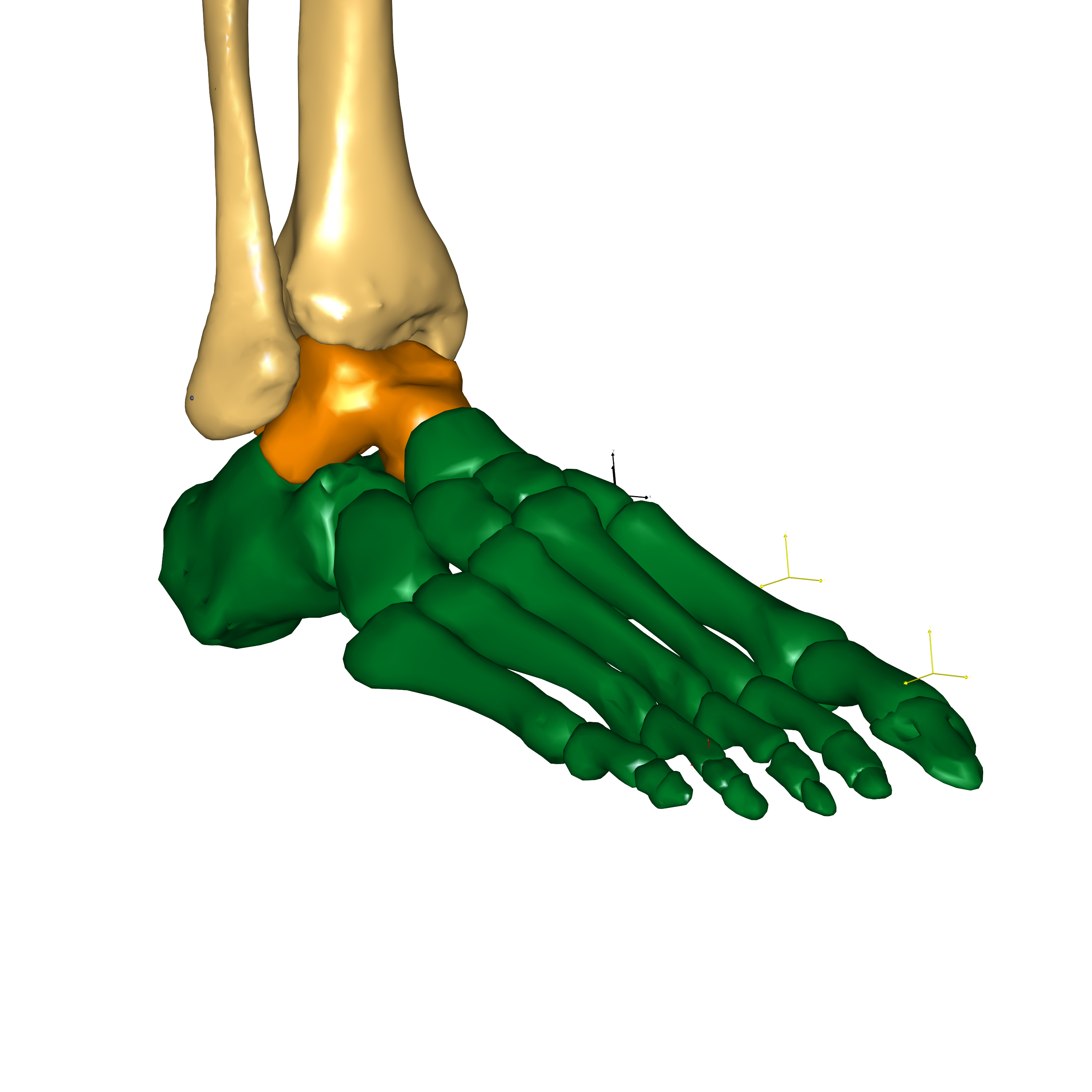
Fig. 11 Rigid foot configuration#
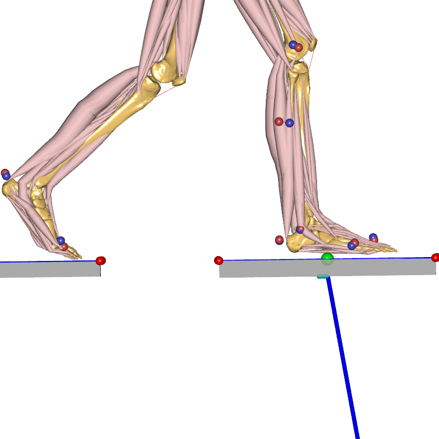
Toe flexion:
#define BM_FOOT_MODEL _FOOT_MODEL_TOE_FLEX_GM_: This model adds flexion-extension degree of freedom at all the toes, that is, the Metatarsophalangeal joints. Each toe is included as a rigid segment, lumping the constituent phalanges. So, there are 7 segments in this model (talus, rigid part, and 5 toes). Furthermore, the motion of the 5 toes is constrained to have the same joint angle, thereby, adding just one degree of freedom for toe flexion when comparing to the rigid foot model. This model can improve kinematics in applications such as gait by allowing bending of toes. The motion of the toes can be driven by motion capture data, for example, by using a toe tip marker, or automatically through the RotationPenetrationCombiDriver class template that prevents penetration of the toes with the ground.Kinematic improvement only
The Toe Flexion configuration is intended for kinematic improvements only. Please don’t use it to evaluate intrinsic loads in the foot!
Each metatarsophalangeal joint carries joint actuators and reaction force to compensate for the lack of ligaments in this model. The reactions can be optionally switched off by setting
#define BM_FOOT_MODEL_TOE_FLEX_GM_REACTION OFF.
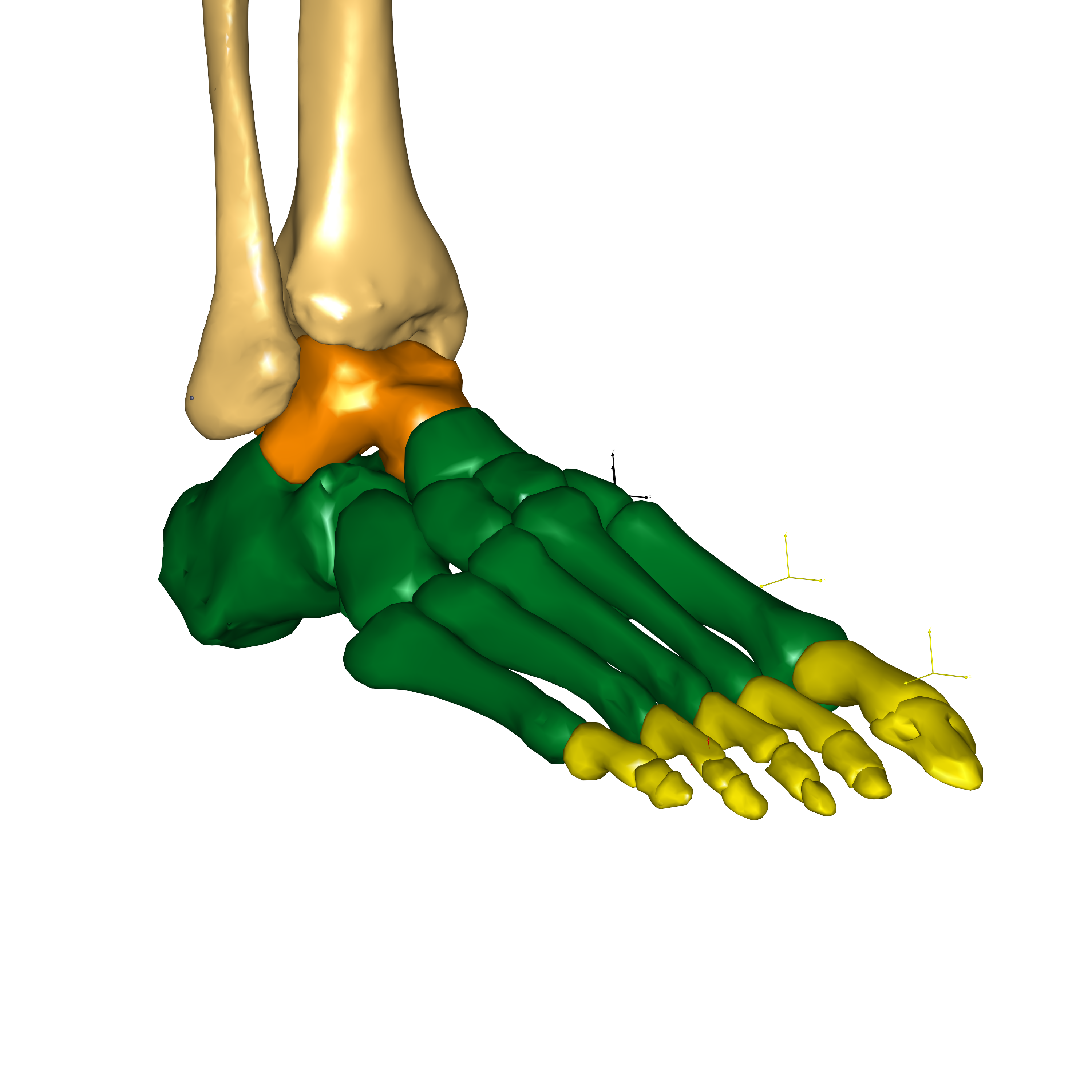
Fig. 12 Toe flexion configuration#
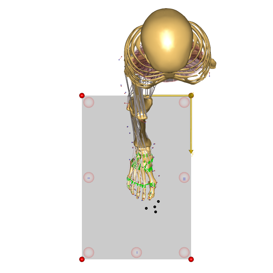
Detailed foot model:
#define BM_FOOT_MODEL _FOOT_MODEL_DETAILED_GM_: This is the full-blown detailed foot model with 26 segments, all the intrinsic muscles and ligaments. This is a highly complex model and is present as a beta configuration. The model is intended for studying the foot in detail and users must be prepared to understand and solve some of the challenges that come with driving such a detailed model.
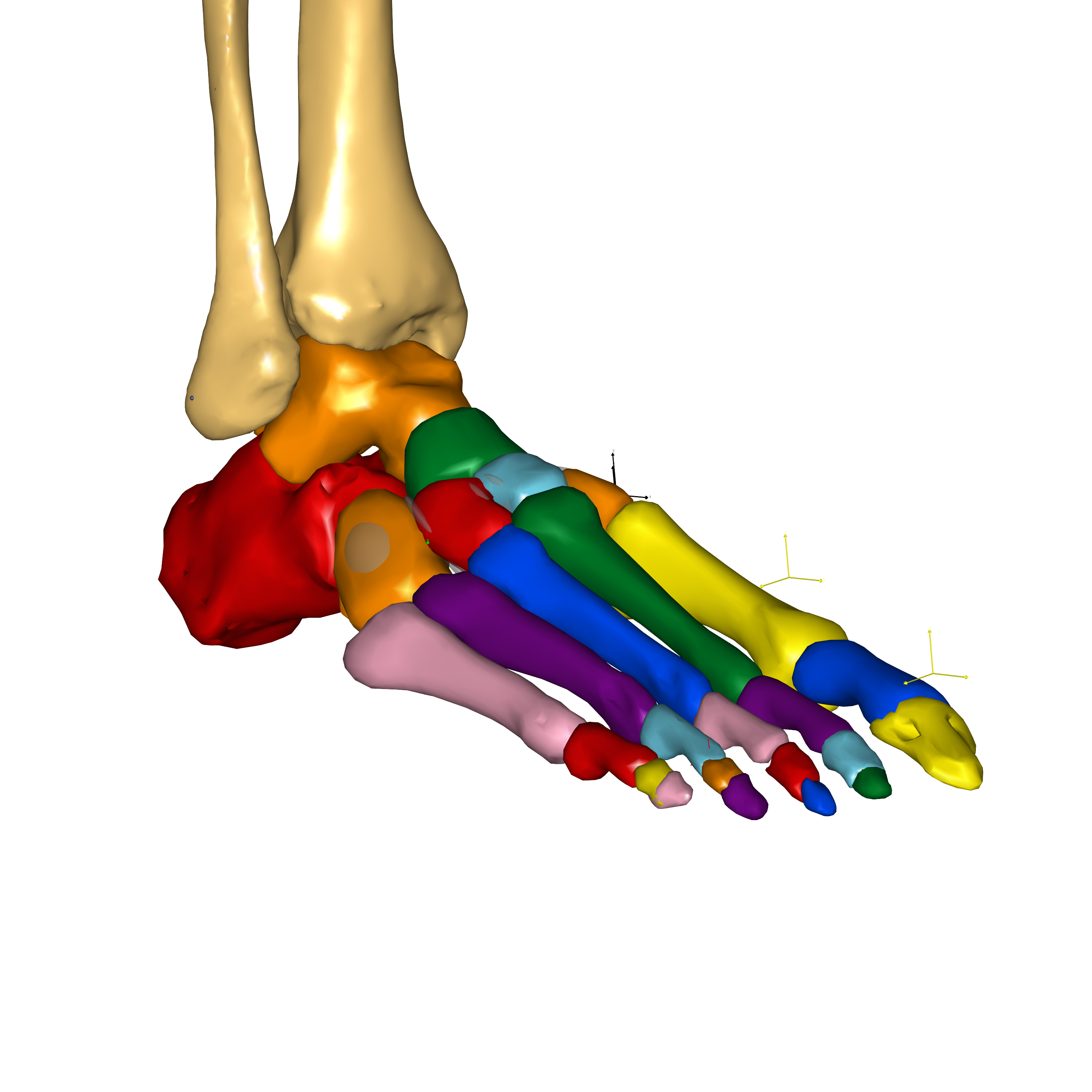
Fig. 13 Detailed foot configuration#
Complex model:
The detailed GM Foot model is very complex and not recommended for beginners in musculoskeletal modeling and AnyBody.
Muscle Switch#
The muscle behavior in the GM foot model can be controlled by switches for the foot muscle, for example, #define BM_FOOT_MUSCLES_LEFT _MUSCLES_SIMPLE_.
The switch defaults to the corresponding leg muscle choice. Currently, the GM foot model can work with simple muscle model. The switch allows the foot
muscles to be set to 3 element Hill muscle model, however the user must provide a calibration routine for the Hill muscle models in the foot.
This switch allows the user to control the foot muscles independently of the leg muscles. Please note that the foot muscles can only be included
if leg muscles are also enabled.
Usage#
The GM foot model can be used with the TLEM 2.2 (or later) leg model and requires AMMR 4.0 or later.
The rigid configuration of the GM foot model is the default foot model for the TLEM leg since AMMR 4.0. To use another configuration of the GM foot model, you can simply add a BM statement in your model:
Main = {

   // Add body model configuration. E.g.
   #define BM_FOOT_MODEL _FOOT_MODEL_TOE_FLEX_GM_
   // possible options:
   // #define BM_FOOT_MODEL _FOOT_MODEL_RIGID_GM_
   // #define BM_FOOT_MODEL _FOOT_MODEL_DETAILED_GM_

};
The model tree is structured to conveniently switch between the different foot configurations
with minimal input from the user. Intrinsic foot segments are collected inside the Foot folder,
Main.HumanModel.BodyModel.Right.Leg.Segments.Foot. In the rigid and toe flexion
configuration that don’t have all the intrinsic segments, reference nodes for all the intrinsic
segments are created on the corresponding lumped segment, for example,
Main.HumanModel.BodyModel.Right.Leg.Segments.Foot.RigidPart.Calcaneus.
Such reference nodes are accompanied by reference pointers under Segments.Foot folder.
That is, Main.HumanModel.BodyModel.Right.Leg.Segments.Foot.Calcaneus is the calcaneus segment
in the detailed foot configuration, whereas it is a pointer to the reference node
Main.HumanModel.BodyModel.Right.Leg.Segments.Foot.RigidPart.Calcaneus in the
rigid and toe flexion configuration.
The user is advised to avoid using the name of the rigid or lumped part when creating reference pointers in their models. That is, it is recommended to work with the foot model in the following manner:
AnyRefNode &MyNode = Main.HumanModel.BodyModel.Right.Leg.Segments.Foot.Calcaneus.HeelNode;
// Or
Main.HumanModel.BodyModel.Right.Leg.Segments.Foot.Calcaneus.HeelNode = {
  AnyRefNode MyNode = {};
};
The above code will work in all the foot model configurations.
Furthermore, if the foot model configuration is switched from the TLEM foot model to one of the GM foot model configuration, there may be errors concerning unresolved object in the foot model. These should be fixed by updating the path to include the intrinsic foot segment as shown above.
Ground reaction force and moments#
The class templates for applying/predicting ground reaction force and moments (GRF&M) have been updated to facilitate switching between the different foot model configurations. C3D-based mocap models with force plate data apply the measured GRF&M to calcaneus and the 5 distal phalanges through recruited actuators. Depending on the configuration of the foot model, these may point to the same rigid segment or to individual segments. Such a configuration is acceptable for the analysis of the leg, but it’s not adequate to study the intrinsic loads in the foot model, for example, with the detailed foot model or the toe flexion model as the foot model is effectively treated as a rigid foot during inverse dynamics analysis.
Likewise, the class template for creating foot contact nodes, which is used in the GRF prediction class template, has also been updated. The contact nodes on the foot are created on the corresponding foot segments, which may be individual segments or pointers to the same segment depending on the configuration of the foot model.
Caution:
The current set up of force plates in C3D mocap models and the foot model configurations doesn’t allow studying the intrinsic joint and muscle forces of the model.
If you are interested in studying the intrinsic load in the foot model, GRF prediction presents a more suitable approach to distribute the GRF among the foot segments. Ideally, you would like to use measured force plate data and apply GRF prediction between the foot and the force plate. This is planned for the future.
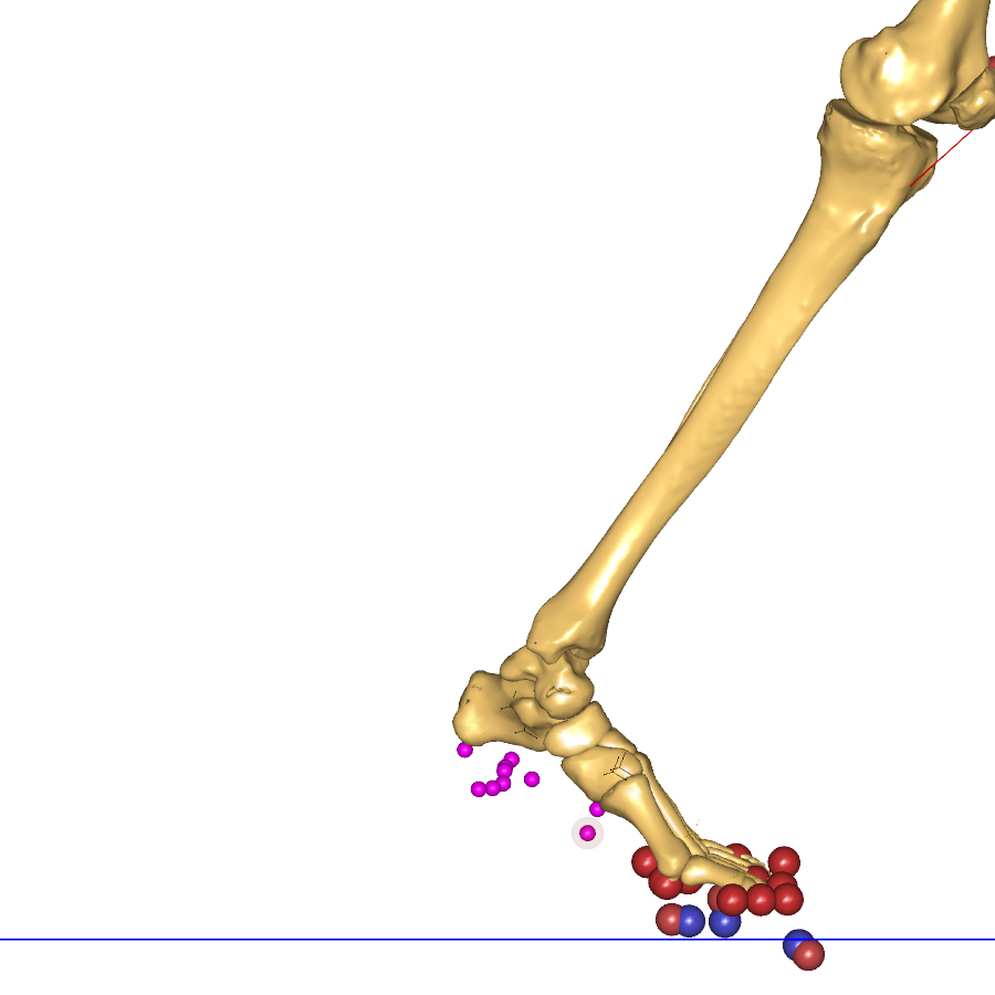
Application examples using the GM foot model#
Model structure#
The detailed foot model includes 26 rigid segments representing all the bones of the human foot (except the sesamoid bones), namely:
Talus, Calcaneus, Cuboid, Navicular, Medial cuneiform, Intermediate cuneiform, Lateral cuneiform, First metatarsal, Second metatarsal, Third metatarsal, Fourth metatarsal, Fifth metatarsal, First proximal phalange, First distal phalange, Second proximal phalange, Second medial phalange, Second distal phalange, Third proximal phalange, Third medial phalange, Third distal phalange, Fourth proximal phalange, Fourth medial phalange, Fourth distal phalange, Fifth proximal phalange, Fifth medial phalange, Fifth distal phalange.
It includes the following joints and kinematic constraints:
Talocrural and Subtalar joint [20], Talonavicular joint, Calcaneocuboid joint, Medialcuneonavicular joint, Intermediate and lateral cuneonavicular joints, First tarsometatarsal joint, Second, third and fourth tarsometatarsal joints, Fifth tarsometatarsal joint, Metatarsophalangeal joints, Interphalangeal joints, Toe flexion rhythm, Intertarsal contact, Metatarsal head contact, Metatarsal transverse arch, Tarsal transverse arch, Longitudinal medial arch, Longitudinal lateral arch.
The GM-Foot model also includes the following additional ligaments:
Collateral (tibiotalar anterior, tibiotalar posterior, tibiocalcaneal and tibionavicular, and the lateral group constituted of the talofibular anterior, talofibular posterior and talocalcaneal), Deep metatarsal transverse, Plantar fascia, Long plantar, Calcaneo cuboid plantar, Calcaneo navicular plantar, Tarsal ligaments ( Talonavicular dorsal, Bifurcate, Calcaneocuboid dorsal, Cuneonavicular dorsal 1, 2 and 3, Cuneonavicular plantar 1, 2 and 3, Intercuneiform dorsal 1 and 2, Cuneocuboid dorsal, Intercuneiform plantar 1 and 2, Cuneocuboid plantar, Cuboideonavicular dorsal, Cuboideonavicular plantar, Tarsometatarsal dorsal 1 to 8, Tarsometatarsal plantar 1 to 7, Intermetatarsal dorsal 1, 2 and 3, Intermetatarsal plantar 1, 2 and 3) and Phalangeal ligaments
The muscles of the foot can be divided into two groups: the intrinsic muscles and the extrinsic muscles. All the extrinsic muscles come from the TLEM leg model of the AMMR. The intrinsic foot musculature is constituted of the following muscles:
abductor hallucis (ABDH), flexor hallucis brevis medialis (FHBM) and lateralis (FHBL), adductor hallucis transverse (ADHT) and oblique (ADHO), abductor digiti minimi (ABDM), flexor digiti minimi brevis (FDMB), dorsal interosseous (DI), plantar interosseous (PI), flexor digitorum brevis (FDB), lumbricals (LB), quadratus plantar medialis (QPM) and lateralis (QPL), extensor hallucis brevis (EHB), extensor digitorum brevis (EDB)
More information can be found online:
The new Glasgow-Maastricht AnyBody foot model (Sylvain Carbes, 20. September, 2012)
This webcast presents a detailed AnyBody musculoskeletal foot model which includes all bones and joints of a real foot. Developed in collaboration with Glasgow Caledonian University and University Hospital Maastricht and referred to as the “Glasgow-Maastricht foot model” this model can be driven by motion capture data and uses combined force plate/pressure plate for accurate loading of the different joints. Built-in scaling allows the user to reproduce principal foot deformities such as flat foot and hallux valgus. The high detail level of the model and a built-in scaling protocol allows the user to investigate a wide range of parameters like joints motion and load, muscles activation, both in healthy and pathologic feet.
References used as input:
Arampatzis, S. et al., Strain and elongation of the human gastrocnemius tendon and aponeurosis during maximal plantarflexion effort. J Biomech, 38(4):833–841, Apr 2005.
Arndt, P. et al., Intrinsic foot kinematics measured in vivo during the stance phase of slow running. J Biomech, 40(12):2672–2678, 2007.
Bandholm, T et al., Foot medial longitudinal-arch deformation during quiet standing and gait in subjects with medial tibial stress syndrome. J Foot Ankle Surg, 47(2):89–95, 2008.
Bloome, DM et al., Variations on the insertion of the posterior tibialis tendon: a cadaveric study. Foot Ankle Int, 24(10):780–783, Oct 2003.
Cailliet, R. The Illustrated Guide to Functional Anatomy of the Musculoskel. Sys.. D J R Evans, 2004.
Cheung, JT et al., Three-dimensional finite element analysis of the foot during standing–a material sensitivity study. J Biomech, 38(5):1045–1054, May 2005.
Fernandes, R. et al., Tendons in the plantar aspect of the foot: Mr imaging and anatomic correlation in cadavers. Skeletal Radiol, 36(2):115–122, Feb 2007.
Funk, JR et al., Linear and quasi-linear viscoelastic characterization of ankle ligaments. J Biomech Eng, 122(1):15–22, Feb 2000.
Kanatli, U. et al., Evaluation of the transverse metatarsal arch of the foot with gait analysis. Arch Orthop Trauma Surg, 123(4):148–150, May 2003.
Kitaoka, HB, et al., Mat properties of the plantar aponeurosis. Foot Ankle Int, 15(10):557–560, 1994.
Kura, H, et al., Quant. analysis of the intrinsic muscles of the foot. Anat Rec, 249(1):143–151,1997.
Lundberg and O.K. Svensson. The axes of rotation of the talocalcaneal and talonavicular joints. The Foot, 3(2):65 – 70, 1993.
Lundgren, P, et al., Invasive in vivo measurement of rear-, mid- and forefoot motion during walking. Gait Posture, 28(1):93–100, Jul 2008.
MacWilliams, BA, et al., Foot kinematics and kinetics during adolescent gait. Gait Posture, 17(3):214–224, Jun 2003.
Mengiardi, B, et al., Spring ligament complex: Mr imaging-anatomic correlation and findings in asymptomatic subjects. Radiology, 237(1):242–249, Oct 2005.
Moraes do Carmo, CC, et al., Anatomical features of plantar aponeurosis: cadaveric study using ultrasonography and magnetic resonance imaging. Skeletal Radiol, 37(10):929–935, Oct 2008.
Netter, FH. Atlas der Anatomie des Menschen 3nd. Georg Thieme Verlag Stuttgart, 2003.
Pastore, D, et al., Complex distal insertions of the tibialis posterior tendon: detailed anatomic and mr imaging investigation in cadavers. Skeletal Radiol, 37(9):849–855, Sep 2008.
Patil, V. et al. Morphometric dimensions of the calcaneonavicular (spring) ligament. Foot Ankle Int, 28(8):927–932, Aug 2007.
Patil, V. et al., Anatomical variations in the insertion of the peroneus (fibularis) longus tendon. Foot Ankle Int, 28(11):1179–1182, Nov 2007.
Picard, M et al., orthopedic physical assessment 3rd edition (1997) wb saunders company,philadelphia 805 pp. 49.95. Journal of Hand Therapy, 11(4):286 –, 1998.
Saeki, J, et al., Force Generation on the Hallux Is More Affected by the Ankle Joint Angle than the Lesser Toes: An In Vivo Human Study. Biology, 10(1), 2021.
Siegler, S, et al., Mechanics of the ankle and subtalar joints revealed through a 3d quasi-static stress mri technique. J Biomech, 38(3):567–578, Mar 2005.
Sooriakumaran, P and Sivananthan, S. Why does man have a quadratus plantae? a review of its comparative anatomy. Croat Med J, 46(1):30–35, Feb 2005.
Stagni, R., et al., Ligament fibre recruitment at the human ankle joint complex in passive flexion. J Biomech, 37(12):1823–1829, Dec 2004.
Taniguchi, A. et al., Anat. of the spring ligament. J Bone Joint Surg Am, 85-A(11):2174–2178, 2003.
Ward, KA and R. W. Soames. Morphology of the plantar calcaneocuboid ligaments. Foot Ankle Int, 18(10):649–653, Oct 1997.
Winson, IC., et al., Metatarsal motion. The Foot, 5(2):91 – 94, 1995.
Winson, IC., et al., Passive regulation of impact forces in heel-toe running. Clin Biomech (Bristol, Avon), 13(7):521–531, Oct 1998.