
Ground Reaction force prediction#
Background#
Motion capture data is often recorded without force plates. In traditional inverse dynamics, this would make it impossible to perform a dynamic analysis. However, AnyBody has the possibility to predict ground reaction forces (GRF), so you can make inverse dynamics models based on recorded motion without GRF force measurement (Fluit et al., 2014; Jung et al., 2014).
GRF prediction relies on conditional contacts added to the feet of the model. The conditional contacts work as force actuators to generate the normal and frictional forces necessary to balance model. Mathematically, the actuators are modeled similarly to muscles, and the muscle recruitment optimization determines the contact forces. The effect is that the model will utilize the ground reactions if that can minimize the muscle activity.
Adding conditional contacts to a model can be rather complex, but we have created an AnyScript class template that makes the process much easier. The class template will generate all the necessary AnyScript code. Thus, adding GRF prediction is similar to adding force plates to a model.
This new functionality is now part of the AnyBody Managed Model Repository (AMMR).
Adding ground force prediction to a model#
The GRF example model is already preconfigured to use the GRF prediction. But if you need to add GRF prediction to new model the following outlines the procedure.
Including the class templates#
The class template is already included in the AnyMoCap framework, so this step can be skipped. However, when using GRF prediction in other models it is necessary to include the following line at the beginning of the model:
#include "<ANYBODY_PATH_AMMR>/Tools/GRFPrediction/FootPlateConditionalContact.any"
Adding the GRF prediction classes#
In the AnyMoCap models GRF prediction is enabled by setting the following setting:
#define MOCAP_USE_GRF_PREDICTION ON
The next step is to add the class template to generate the AnyScript code for GRF prediction. These classes replaces the Force plate classes in the AnyMoCap model.
// EXCLUDE THE EXISTING C3D FORCE PLATES
// ForcePlateAutoDetection Plate1(
// PLATE_NO=1,
// HeightTolerance = 0.07,
// VelThreshold = 2.2,
// FORCEPLATE_TYPE = 4,
// ALLOW_MULTI_LIMB_CONTACT = OFF
// ) = { };
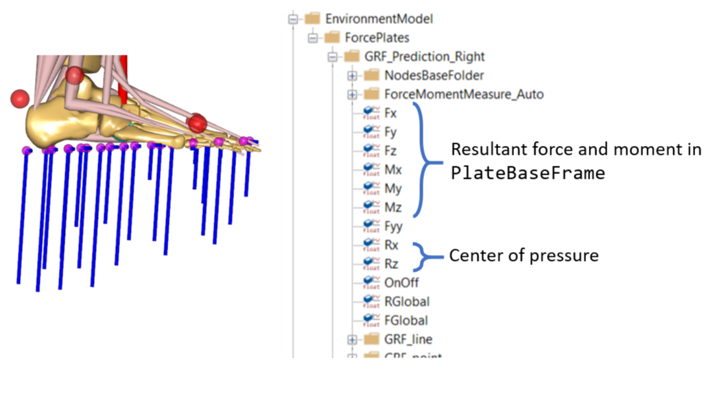
FootPlateConditionalContact GRF_Prediction_Right(
NORMAL_DIRECTION = "Y",
NUMBER_OF_NODES = 25,
NODES_FOLDER = FootNodes,
PLATE_BASE_FRAME = Main.EnvironmentModel.GlobalRef
) = {
CreateFootContactNodes25 FootNodes(
foot_ref=Main.HumanModel.BodyModel.Right.Leg.Seg.Foot
) = {};
};
See below for more information on the GRF prediction classes.
Setting up new residuals (Hand of God)#
Adding conditional contacts to the feet is not enough. The AnyMoCap model comes reactions forces applied to the pelvis. These are the reactions that carry any inconsistencies between the model and force plate data, and they must be removed for ground reaction force prediction.
Instead, we apply another type of residuals to the model, so the solver does not fail if the model fails to balance. These residuals are implemented as recruitment actuators from pelvis to the global reference frame. These actuators are implemented similarly to how muscles work. However, they are very weak, so the recruitment solver will only activate them if nothing else can balance the model.
In the AnyMoCap models the new residuals are activated by default when
MOCAP_USE_GRF_PREDICTION is set to ON. So no need to do anything.
In other models the Weak residuals must be added manually, or by including the following file in your model:
Main.ModelEnvironmentConnection  = {
    #include "<ANYBODY_PATH_AMMR>/Tools/GRFPrediction/WeakResiduals.any"
};
The file WeakResiduals.any does the job of removing the ‘Hand of God’ and adding
the new, weak residuals. Again this is handled automatically in the AnyMoCap
based models.
Running the model#
The model is run in the same way as other models. The only difference is that it now uses GRF prediction instead of force plates data.
It may be necessary to adjust the parameters of the GRF prediction class to obtain a good prediction of the ground reactions. This is especially important around heel strike and toe-off, where the model can have problems.
GRF prediction trouble shooting#
Here are some things to check if a GRF prediction model fails running inverse dynamic:
Direction of gravity is it specified correctly? this needs to be correct in two places the Gravity property of the study in the LabSpecific.any data and in the definition of the force plates setting the variable
NORMAL_DIRECTION.In the file Forceplate_GRFprediction.any try to increase the property
LimitDistHigh, this controls when contact can occur so if the number is higher the foot do not need to be as close to the ground before contact can occur, see also LimitVelHigh it controls speed limit.Unrealistic accelerations of the model could be the reason if your data are not filtered correctly
The model is using a weak residual to the ground that helps holding the balance in the model if the feet contact are not enough, this is defined in the file “Tools/GRFPrediction/Weakresidual.any” here you can increase the strength of the artificial muscles, but this will lead to higher residuals so be careful.
A closer look at the GRF template#
Finally, we can take a closer look at the FootPlateConditionalContact template.
FootPlateConditionalContact GRF_Prediction_Right(
    NORMAL_DIRECTION = "Y",
    NUMBER_OF_NODES = 25,
    NODES_FOLDER = FootNodes,
    PLATE_BASE_FRAME = Main.EnvironmentModel.GlobalRef
) = {
    CreateFootContactNodes25 FootNodes(
        foot_ref=Main.HumanModel.BodyModel.Right.Leg.Seg.Foot
    ) = {};
};
It consists of two parts; a top level class template
(FootPlateConditionalContact) that generate the conditional-contact code.
This code needs a few important arguments. The ground plane
(PLATE_BASE_FRAME) is a reference system where the ground plane is located.
Together with arguments NORMAL_DIRECTION this specifies the surface the
model is walking on. Another important argument is the NODES_FOLDER, which
is a folder that contains all the contacts points.
The contact points can be created manually, but to avoid this we use another
class-template (CreateFootContactNodes25) to create the nodes automatically.
As the name says it creates 25 nodes in the foot coordinate system. This part is
specific to the model implementation. One could also imagine class-templates
that produce a higher number of nodes or nodes in positions that corresponds to
particular shoes or on other body parts.
Of course, there are also many options that can be tweaked and adjusted.
Class templates: FootPlateConditionalContact#
Obligatory members are marked with < > and optional values are marked with
[ ]. Default values are bold:
Usage:
FootPlateConditionalContact <Object_name>(
     NORMAL_DIRECTION     = "<X|Y|*Z>",
     NUMBER_OF_NODES      = [*1..200],
     NODES_BASE_FOLDER    = <AnyFolder> ,
     PLATE_BASE_FRAME     = <AnyRefFrame>,
     SHOW_TRIGGER_VOLUME = [*0|1] ) =
{
  Settings =
  {
    [ LimitDistLow = -0.10;               ]
    [ LimitDistHigh = 0.04;               ]
    [ LimitVelHigh = 0.8;                 ]
    [ GroundVelocity = {0.0, 0.0, 0.0};   ]
    [ Strength = 200;                     ]
    [ FrictionCoefficient = 0.5;          ]
    [ ScaleFactor = 1;                    ]
    [ ForceVectorDrawScaleFactor = 0.0005;]
  };
Class arguments:
PLATE_BASE_FRAME:Is a AnyRefFrame object where the ground planes is attached.
NORMAL_DIRECTION:Defines the normal direction of the ground plane the in PLATE_BASE_FRAME coordinate system.
NODES_BASE_FOLDER:The folder where all contact nodes are located below. contact nodes must be AnyRefNodes named must be named
Node#where#is a number. Eg.Node1` ...``Node24NUMBER_OF_NODES:The number of contact nodes to expect within
NODE_BASE_FRAMESHOW_TRIGGER_VOLUME:Visualize the volume where contacts may be triggered.
GLOBAL_REF:The global reference. This must be set if the global reference is not
Main.EnvironmentModel.GlobalRef
Optional initialization:
Settings.LimitDistLow:Lower bound of the contact detection volume.
Settings.LimitDistHigh:Upper bound of the contact detection volume.
Settings.LimitVelHigh:Velocity threshold for contact detection.
Settings.Strength:Strength of the contact elements.
Settings.FrictionCoefficient:Friction coeficient of the contact elements. This adds limits to the amount of friction force which can be recruited.
Settings.ForceVectorDrawScaleFactor:Scale factor for the drawing of the GRF force vector