
Lesson 2: Using motion capture data#
In the previous lesson, we explored how a large and complex AMMR model can be driven using motion capture data. Now, let’s take a step back and start building our own simple model driven by motion capture data.
Please download and save this
AnyBody Model of a pendulum and this file
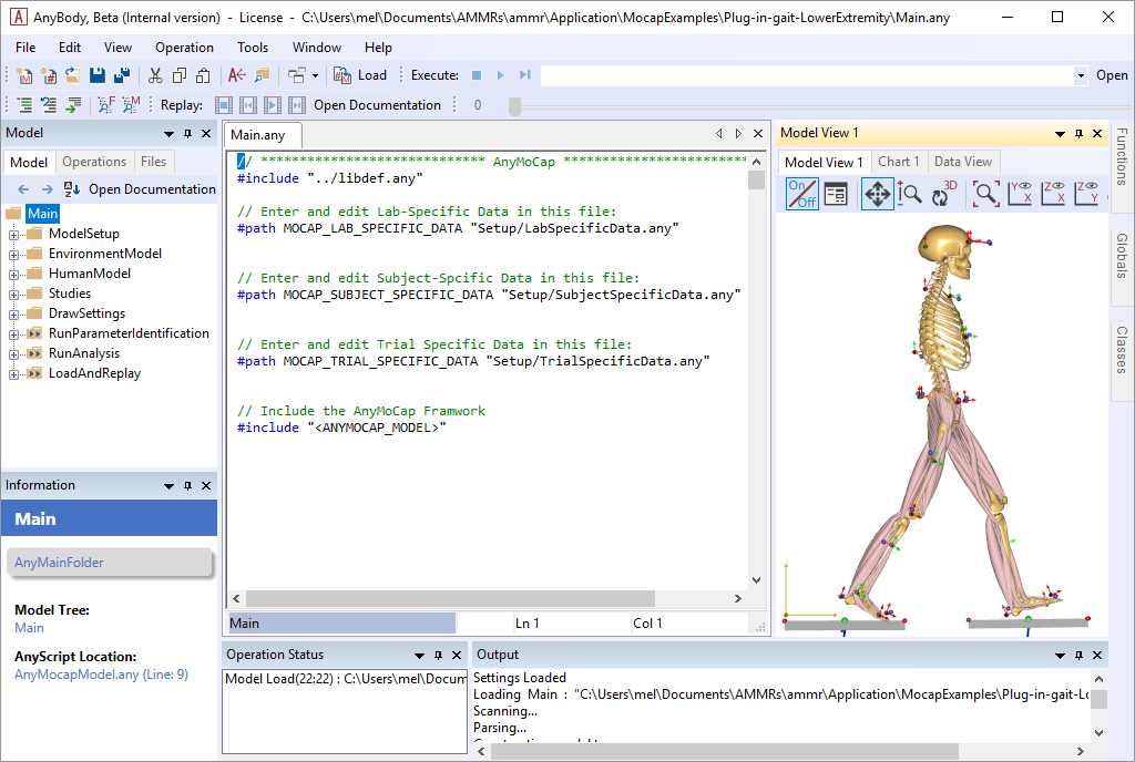
pendulum.c3d in the same folder. Load
the model into AnyBody and open a new model view. You should see a vertical
segment with a point at each end. It is, in fact, a pendulum model linked to the
global reference frame by a revolute joint at its upper end point. We use this
example because it is very simple and has a remote similarity with a human limb.
A hinged pendulum, like a forearm hinged at the elbow, will have just one DoF,
hence only one driver is needed to drive its motion. The class AnyKinMotion with
a polynomial driver function is already inserted in the model as its driver.
Refer to Lesson 5 in the tutorial How to Write AnyScript
for more information about this driver.
In the following we will drive the pendulum using motion capture data instead of using this driver.
Driving Using Motion Capture Data#
Now, place the cursor in the editor window just before the AnyKinMotion
object, click the Classes tab (on the right side of the screen), unfold the class list, and locate the
AnyInputC3D class. Right-click the class and choose “Insert Class
Template”.
AnyInputC3D <ObjectName> =
{
  FileName = "";
  //ReadAllDataOnOff = On;
  //TruncateExtraCharsInNamesOnOff = On;
  //MakeNameUniqueStr = "_";
  //PointsScaleFactor = 1.0;
  //ConstructModelOnOff = On;
  //ConstructChartOnOff = On;
  //ConstructWeightFunUsingResidualOnOff = Off;
  //GapFillUsingResidualsOnOff = Off;
  //MarkerUseAllPointsOnOff = Off;
  //MarkerUseCamMaskOnOff = On;
  //MarkerIndices = ;
  //MarkerLabels = ;
  //MarkerFilterIndex = 0;
  //ProcessedDataFilterIndex = 0;
  //AnalogFilterIndex = -1;
  /*Filter =
  {
  AutomaticInitialConditionOnOff = On;
  FilterForwardBackwardOnOff = On;
  N = 2;
  W = ;
  Fs = 0.0;
  Fc = {10.0};
  Type = LowPass;
  };*/
  //WeightThreshold = 0.0;
  //WeightOutput = {{0.0, 1.0}, {0.0, 1.0}, {0.0, 1.0}};
  //WeightTransitionTime = 0.1;
  //SearchAndReplace = ;
  //WriteMarkerDataToFilesOnOff = Off;
  //MarkerScaleXYZ = {0.025, 0.025, 0.025};
  //MarkerRGB = {0.65, 0.65, 0.65};
  //MarkerDrawOnOff = On;
  //MarkerInterPolType = Bspline;
  //MarkerBsplineOrder = 4;
};
As you can see, the class has a lot of settings, but for now we shall
only use two of them, namely FileName and ConstructChartOnOff. We also
give a name to the object:
AnyInputC3D C3D = {
  FileName = "pendulum.c3d";
  //TruncateExtraCharsInNamesOnOff = On;
  //MakeNameUniqueStr = "_";
  //PointsScaleFactor = 1;
  //ConstructModelOnOff = On;
  ConstructChartOnOff = Off;
};
ConstructChartOnOff instructs the C3D object to not draw 3D
trajectories.
Now, try loading the model again and run the Kinematics operation. You should get the following error message:
Time, 't', has an invalid value for this interpolation
This is because C3D files contain marker trajectories covering a certain time span and what goes on outside that interval is undefined. Furthermore, the very beginning and very end of that time span may not be useful for the motion interpolation due to initial transients.
If you have a C3D file of unknown duration, you need to determine its start and
end times so that AnyBody can analyze it. In this case, we can already load the
model, which makes this task easy. If you have a model that cannot be loaded, a simple way
to allow AnyBody to load the file is to temporarily disable the study section of
your model. This will eliminate conflicting start and end times in the study.
Simply select the study section and click the “Comment out” tool button above
the editor window (or press Ctrl+Shift+k):
// The study: Operations to be performed on the model
// AnyBodyStudy MyStudy = {
//   AnyFolder &Model = .MyModel;
//   Gravity = {0.0, -9.81, 0.0};
// };
Now the model should load with no problems, and you can go to the Model tree view in the left hand side of the screen, click the Model tab and unfold MyModel tree down to the C3D object as shown below.
A bit down in this object you find a folder named “Header”. When you unfold it you get access to a number of basic properties of the C3D file. Each time you double-click a property, a window will pop up and give you its value. The important properties in question are these:
FirstFrameNo = 1
LastFrameNo = 1000
VideoFrameRate = 100
This shows that the file has a total of 1000 frames at a frame rate of 100 frames/sec, i.e. the simulation time spans ten seconds. We can now go to the editor window and remove the temporary double slashes in front of each line to uncomment the study section and insert specifications of simulation time:
AnyBodyStudy MyStudy = {
  AnyFolder &Model = .MyModel;
  Gravity = {0.0, -9.81, 0.0};
  tStart = 0.05;
  tEnd = 9.95;
};
There is also an automated way to handle the problem. The frame rate
variables we have just processed manually can also be referred to
directly in the study section, such that the tStart and tEnd parameters
automatically adapt to the C3D file. Try this instead:
AnyBodyStudy MyStudy = {
  AnyFolder &Model = .MyModel;
  Gravity = {0.0, -9.81, 0.0};
  AnyIntVar FirstFrame = Main.MyModel.C3D.Header.FirstFrameNo;
  AnyIntVar LastFrame = Main.MyModel.C3D.Header.LastFrameNo;
  tStart = FirstFrame/Main.MyModel.C3D.Header.VideoFrameRate+2*Kinematics.ApproxVelAccPerturb;
  tEnd = LastFrame/Main.MyModel.C3D.Header.VideoFrameRate-2*Kinematics.ApproxVelAccPerturb;
};
Notice that we start the simulation 2*Kinematics.ApproxVelAccPerturb
after the beginning of the recorded motion and we end it similarly
before the end of the recording. The variable
Kinematics.ApproxVelAccPerturb contains information about the
algorithm’s necessary elbow room on each side of the analyzed interval.
This eliminates possible numerical trouble with end points.
Now the model should load and the Model View window will display a small, grey dot to the right of the pendulum end.
The small dot is in fact the single marker contained in Pendulum.c3d. A
typical file from a real motion capture experiment can contain dozens of
markers, but in the interest of simplicity we have just included a single one
here. The AnyInputC3D object automatically creates the small dots and the
drivers necessary to move them around as they were recorded. If you run the
Kinematics operation, you will see the pendulum move as before, while the marker
performs an oscillating motion back and forth
So how do we get the marker to drive the pendulum? This can be done
quite easily with the AnyKinDriverMarker object. The steps are:
Remove the existing driver that makes the pendulum rotate.
Drive the marker point,
P1, on the pendulum to follow the data recorded in the C3D file.
Start by selecting the existing AnyKinMotion driver and comment it out
of the model. That takes care of step 1.
Then click the Classes tab on the right side of the screen,
insert a new AnyKinDriverMarker template, and give it a name:
AnyKinDriverMarker <ObjectName> =
{
  //viewKinMeasure.Visible = Off;
  //MeasureOrganizer = ;
  //CType = ;
  //WeightFun = ;
  //DriverPos0 = ;
  //DriverVel0 = ;
  //DriverAcc0 = ;
  AnyRefFrame &<Insert name0> = <Insert object reference (or full object definition)>;
  //AnyRefFrame &<Insert name1> = <Insert object reference (or full object definition)>;
  //AnyParamFun &<Insert name0> = <Insert object reference (or full object definition)>;
};
Just as before, the AnyKinDriverMarker object needs to know what to
drive and what to drive it with. The “what to drive” part is the
position of P1 on the pendulum. This is specified with the first
reference frame in the object:
AnyKinDriverMarker C3DMotion  =
{
  //viewKinMeasure.Visible = Off;
  //MeasureOrganizer = ;
  //CType = ;
  //WeightFun = ;
  //DriverPos0 = ;
  //DriverVel0 = ;
  //DriverAcc0 = ;
  AnyRefFrame &Marker = .Pendulum.P1;
  //AnyRefFrame &<Insert name1> = <Insert object reference (or full object definition)>;
  //AnyParamFun &<Insert name0> = <Insert object reference (or full object definition)>;
};
The marker coordinates in the C3D file are recorded in the laboratory
coordinate system, which we shall assume is our global reference frame.
Driving from GlobalRef is default in linear measures, so we need not
mention GlobalRef explicitly in the AnyKinDriverMarker object.
We are going to drive the point directly by means of the interpolation
function specifying the marker trajectory in the C3D object. First, give
a reasonable name to the AnyParamFun and remove the stuff after the
equality sign.
Then click the Model tab in the tree view on the left hand side of the editor
window, unfold the MyModel branch and subsequently the C3D ->
Points -> Markers -> L000 and arrive at PosInterpol as shown
below.
This is the actual interpolation function of the marker in question.
Place the cursor after the equality sign of the AnyParamFun line,
right-click the PosInterpol object, and choose “Insert object name”. You
should get this:
AnyKinDriverMarker C3DMotion  =
{
  //viewKinMeasure.Visible = Off;
  //MeasureOrganizer = ;
  //CType = ;
  //WeightFun = ;
  //DriverPos0 = ;
  //DriverVel0 = ;
  //DriverAcc0 = ;
  AnyRefFrame &Marker = .Pendulum.P1;
  //AnyRefFrame &<Insert name1> = <Insert object reference (or full object definition)>;
  AnyParamFun &Trajectory = Main.MyModel.C3D.Points.Markers.L000.PosInterpol;
};
Now load the model and run the kinematic analysis. You will get the following error message:
ERROR(OBJ.MCH.KIN2): pendulum.any(64): MyStudy.InitialConditions: Model is kinematically over-constrained
It is time to think of the concept of degrees-of-freedom, DoF. A hinged
pendulum, like a forearm hinged at the elbow, will have just one DoF. But the
marker trajectory has three coordinates and therefore wants to drive P1 of the
pendulum in \(x\), \(y\) and \(z\), i.e. two DoFs more than we have available.
There are two possible solutions to this problem. Either we pick only one of the directions given by the marker and let the revolute joint decide the rest, or we have to accept that the pendulum cannot follow the marker completely in all three DoFs, i.e. something has to give.
Driving just one direction would be fairly simple in this case, but in a more complicated model with many markers, the selection of a subset of directions to drive can be a very tedious process.
Another aspect to consider is that marker data are measured and therefore always infested with various types of errors and noise. One of the serious errors in motion capture technology is the so-called soft tissue artifact or skin artifact. It comes from the fact that markers are placed on the skin at some distance from the bone whose motion they are supposed to record. Between the marker and the bone are layers of skin, fat and muscle, so the marker never moves exactly with the bone. It is therefore natural in the model to presume that the connection between the marker and the bone is not a rigid one, and when that is the case, AnyBody will accept drivers on more DoFs than the model actually has.
Resolving the kinematics in the presence of moving markers is somewhat more complicated numerically, so we have to ask for a specific kinematics solver that can handle it. This is done in the study section:
AnyBodyStudy MyStudy = {
  AnyFolder &Model = .MyModel;
  Gravity = {0.0, -9.81, 0.0};
  AnyIntVar FirstFrame = Main.MyModel.C3D.Header.FirstFrameNo;
  AnyIntVar LastFrame = Main.MyModel.C3D.Header.LastFrameNo;
  tStart = FirstFrame/Main.MyModel.C3D.Header.VideoFrameRate+2*Kinematics.ApproxVelAccPerturb;
  tEnd = LastFrame/Main.MyModel.C3D.Header.VideoFrameRate-2*Kinematics.ApproxVelAccPerturb;
  InitialConditions.SolverType = KinSolOverDeterminate;
  Kinematics.SolverType = KinSolOverDeterminate;
};
The two additional lines select a kinematic solver for the InitialConditions and Kinematics operations that will accept more kinematic constraints than the system has DoFs.
Note
See Andersen MS, Damsgaard M, and Rasmussen J. 2007 for detailed information about the algorithm behind the overdeterminate kinematic analysis.
Now you can reload and run the kinematic analysis and you should see the pendulum following the marker movement. You cannot see the marker during the movement because it is hidden inside the pendulum. In fact, the marker is not strictly necessary for the analysis and we can get rid of it altogether by an additional specification in the C3D object:
AnyInputC3D C3D = {
  FileName = "pendulum.c3d";
  //TruncateExtraCharsInNamesOnOff = On;
  //MakeNameUniqueStr = "_";
  //PointsScaleFactor = 1;
  ConstructModelOnOff = Off;
  ConstructChartOnOff = Off;
};
With the unnecessary marker gone from the model, the kinematic analysis runs faster than before. Each marker adds DoFs and constraints to the model, and they require solution time. It is therefore more efficient to leave the markers out unless you really need them.
Now that there is a driver between pendulum and the marker, it is possible
to simultaneously draw both the point on the pendulum and the marker
from the C3D file. To do this, start by placing the cursor inside the
AnyKinDriverMarker object.
Then click the Classes tab on the right side of screen, insert a new
AnyDrawKinMeasure template, remove the properties we will not need and give
it a name:
AnyKinDriverMarker C3DMotion  =
{
  //viewKinMeasure.Visible = Off;
  //MeasureOrganizer = ;
  //CType = ;
  //WeightFun = ;
  //DriverPos0 = ;
  //DriverVel0 = ;
  //DriverAcc0 = ;
  AnyRefFrame &Marker = .Pendulum.P1;
  //AnyRefFrame &<Insert name1> = <Insert object reference (or full object definition)>;
  AnyParamFun &Trajectory = Main.MyModel.C3D.Points.Markers.L000.PosInterpol;

  AnyDrawKinMeasure drw =
  {
    //Label = On;
    //Size = 0.02;
    //Line = On;
  };
};
If you reload the model, you should see something like this:
The blue dot illustrates the marker from the c3d file and the red line
is drawn to illustrate the difference between the point on the segment
and the measured point. Please notice that there is a small ball hidden
inside yellow sphere from the drawing of the segment. The plot also
shows a label “KDM”, which indicates that it is an AnyKinDriverMarker
that is drawn.
The line between the two points and the label can be removed by changing
the Label and Line settings to Off. Let us also change the size of the
dots such that we can see both the point on the segment as well as the
measured point.
AnyDrawKinMeasure drw =
{
  Label = Off;
  Size = 0.07;
  Line = Off;
};
Reloading the model should show you something like this:
Let us briefly investigate the kinematic constraints of our model. Click
the Model tab in the tree view on the left hand side of the screen and
unfold the Joint branch. Inside you find Constraints, and after
unfolding that branch you find the property CType. If you double-click
it, the popup window shows the following:
CType = {Hard, Hard, Hard, Hard, Hard}
CType appears to be a vector with five components, owing to the fact
that a revolute joint has five constraints, and CType specifies that all
of these are Hard. This means that the kinematic solver is not allowed
to violate any of them.
If you similarly locate and unfold the C3DMotion object you again find a
CType, and double-clicking it reveals
CType = {Soft, Soft, Soft}
We have implicitly specified that the joint is a hard constraint while
the marker is a soft constraint. Joints automatically have their
constraint types set to Hard and AnyKinDriverMarker objects
automatically have soft constraints, but these rules can be overridden
by the user by explicit specification of CType in the respective
objects.
In Lesson 3 we investigate how to filter noise out of the measured data.