
Making the Translated AnyScript Model Move#
As previously mentioned, the exported model comes out of SOLIDWORKS and into AnyBody with one degree of freedom. In this lesson, we wil add a driver to this degree of freedom to make the exercise machine move inside AnyBody.
If you did not finish the previous lesson, you can download the finished
AnyScript model file here:
FitnessMachine\_Mate\_Config1.zip
Add an AnyBodyStudy Object and a Kinematic Motion Driver#
We will make these additions to the model in the Main file, but since ‘FitnessMachine.main.any’ was generated by the AnyBody Exporter™ for SOLIDWORKS® (AnyExp4SOLIDWORKS™) and will be overwritten next time we update the translation, we shall make our own copy before editing. We call this new Main file ‘My.FitnessMachine.main.any’.
The first step is to add a study object to the Main file. The study contains the necessary operations that will perform a kinematic analysis, which is how AnyBody moves the model. Let us add an AnyBodyStudy object to make this model work for kinematic and inverse dynamic analyses.
Main =
{
  #include "FitnessMachine.any"

  AnyBodyStudy Study =
  {
    AnyFolder& Model = .FitnessMachine;
    tStart = 0;
    tEnd = 1;
    nStep = 101;
    Gravity = {0, -9.81, 0};
  };
};
Notice how the ‘FitnessMachine’ folder is added by a reference, so that the study object “knows the model” that it must study.
The next step is to add a motion driver to determine the position of the single degree of freedom at every time step and thereby the entire mechanism. The logical and simple choice is to drive the angle of the flywheel. As we saw before, the imported model in AnyBody is almost completely equivalent in structure to the SOLIDWORKS model, so we can use the latter to look for a place to attach the driver.
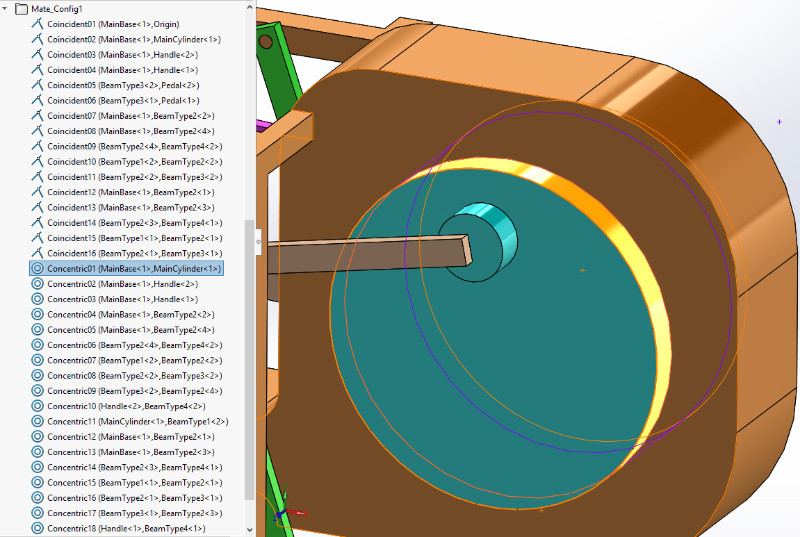
The ‘Concentric01’ mate is a relationship between two cylindrical faces of the
‘MainBase<1>’ and ‘MainCylinder<1>’ components. This mate contains two linear
and two rotational constraints between two different components. So this mate
can still allow two degrees of freedom: 1 translational and 1 rotational
movement. Let us look at the definition of this ‘Concentric01’ mate inside
FitnessMachine.any.
AnyKinEqSimpleDriver Concentric01 =
{
  AnyKinLinear lin =
  {
    AnyRefFrame& base = ...MainBase___1.FitnessMachine_Concentric01;
    AnyRefFrame& target = ...MainCylinder___1.FitnessMachine_Concentric01;
    Ref = 0;
  };
  AnyKinRotational rot =
  {
    AnyRefFrame& base = ...MainBase___1.FitnessMachine_Concentric01;
    AnyRefFrame& target = ...MainCylinder___1.FitnessMachine_Concentric01;
    Type = PlanarAngles;
    Axis1 = z;
    Axis2 = y;
    Axis3 = x;
  };
  MeasureOrganizer = {0, 1, 4, 5};
  DriverPos = {0, 0, 0, 0};
  DriverVel = {0, 0, 0, 0};
  CType = {.._ANY_CTYPE_, .._ANY_CTYPE_, .._ANY_CTYPE_, .._ANY_CTYPE_};
};
We can see that there is one AnyKinLinear and one AnyKinRotational kinematic
measure for this mate. The rotation is obviously related to the
AnyKinRotational object, so let us use this to define a kinematic driver. We
can do this because the rotational measure ‘rot’ is already measuring the angle.
The PlanarAngles type gives us one real angle and two special out-of-plane
measurements, which are already constrained to be zero, i.e., in-plane, by the
translated code. The remaining real angle, i.e., the first component of the
‘rot’ measure, can be constrained by a driver. We add this to the AnyFolder
FitnessMachine from the Main file.
Main =
{
  #include "FitnessMachine.any"

  FitnessMachine =
  {
    AnyFolder Drivers =
    {
      AnyKinEqSimpleDriver rot_drv =
      {
        AnyKinRotational& rot = ..Mates.Concentric01.rot;
        MeasureOrganizer = {0};
        DriverPos = pi/180*{0};
        DriverVel = pi/180*{180};
      };
    };
  };

  AnyBodyStudy Study =
  {
    AnyFolder& Model = .FitnessMachine;
    tStart = 0;
    tEnd = 1;
    nStep = 101;
    Gravity = {0, -9.81, 0};
  };
};
If you load this modified model, you will see the following warnings.
Model Warning: Study 'Main.Study' contains more reaction forces than rigid-body degrees of
freedom of the segments. The model may be statically indeterminate. There are 122 reactions
and only 96 rigid body degrees of freedom.
Also, if you try to run InverseDynamics analysis for this model, it will cause some kinematic errors. The reason for these warnings and errors is that there are redundant mates, i.e., there are more kinematic constraints than necessary to constrain the model. This is generally unsound and these additional constraints should be eliminated. There is a simple way to try to solve this situation in AnyBody without changing the SOLIDWORKS model. We shall try this first.
Firstly, we change the solver type of the AnyBodyStudy object, so a solver for
over-determinate problems is used. Add the following in
MyFitnessMachine.main.any:
AnyBodyStudy Study =
{
  AnyFolder& Model = .FitnessMachine;
  tStart = 0;
  tEnd = 1;
  nStep = 101;
  Gravity = {0, -9.81, 0};
  InitialConditions.SolverType = KinSolOverDeterminate;
  Kinematics.SolverType = KinSolOverDeterminate;
};
And in the FitnessMachine.any file we change the constraint type to ‘Soft’ for
all kinematic constraints created from mates in the SOLIDWORKS model.
AnyFolder FitnessMachine =
{
  #if (ANYBODY_V1 > 7)|(ANYBODY_V1 == 7 & ANYBODY_V2 > 1)
  AnyComponentDefinition CompDef =
  {
  };
  #endif

  AnyKinEqType _ANY_CTYPE_ = Soft;
  ...
}
The significance of these new specifications is to switch to a kinematic solver algorithm that allows violation of kinematic constraints if these are considered soft, and therefore we define all of the constraints indiscriminately as ‘Soft’.
After reloading the model, you may be able to run ‘Kinematics’ or ‘InverseDynamics’ analysis, but it will give you some warnings saying the mechanical system is kinetically over-constrained. But this modification of solver and constraints types does not guarantee the successful performance of kinematic analysis. Even if you can run your over-constrained model successfully, there is one significant remaining problem: Generally speaking, if there are redundant constraints in your model, it implies that there are also redundant reaction forces in your models, since kinematic constraints and reaction forces are connected one-to-one. In this case, there may not be a unique solution for those unknown reaction terms to be found by the InverseDynamics analysis.
Having too many reactions in a rigid-body dynamics model is similar to what is called “statically indeterminacy” in structural mechanics. To solve such problems, you need to know about the structural deformations to establish the reaction forces and this involves the stiffness of the structures, which we do not have or use in the rigid-body dynamic analysis. To make a unique solution of the forces in rigid-body dynamics, we must reduce the constraint reactions to match the independent set of constraints. In other words, we must remove the redundant constraints and thereby their reactions.
You may ask whether this is a choice of mathematical convenience for the solvers to handle the problem? It is indeed mathematically convenient, but it is also sound engineering practice in mechanism design not to make your mechanisms over-constrained, not even if it is redundant constraints. Manufacturing tolerances could make redundant constraints actually conflict, leading to mechanism locking and extensive wear. Therefore, sound engineering design is to make sure that constraints and reactions do not conflict and it is your task to introduce these engineering design decisions properly into your models.
There are two ways to approach this task: editing your AnyScript model directly or editing your mate definitions in SOLIDWORKS and re-exporting it. We shall here adopt the latter approach.
Removing Redundant Mates in SOLIDWORKS before doing the Translation#
If your SOLIDWORKS CAD model has a very complex structure, then it may be difficult to modify the AnyScript model to remove the redundant constraints. Furthermore, in an interactive design process, you may wish to work with the SOLIDWORKS model and re-export it repeatedly to AnyBody. In this case, it is probably a better choice to solve the redundancy problem directly in the CAD system.
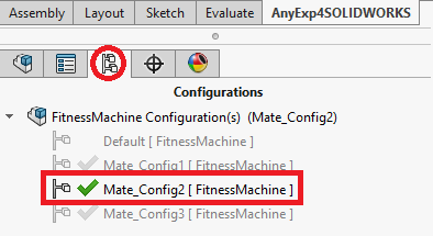
For this purpose, the SOLIDWORKS example model has already been set up
with different configurations. If you open the previous
FitnessMachine\_SOLIDWORKS.zip
file again in SOLIDWORKS, you will see that it already contains two new mate
configurations with the results of the modifications we suggest in order
to remove kinematic redundancy.
We can find the main reason for mate redundancy in SOLIDWORKS by examining several mates, which are used between two different parts in the assembly.
Mate configuration 1:
Firstly, let us look at two mates in the ‘Mate_Config1’ configuration of the top
assembly. All the mates which were used in this configuration can be classified
as one of the standard mate types of SOLIDWORKS. Let us find the mates, which
are defined between the ‘MainBase<1>’ and ‘BeamType2<1>’ components.
Mate Type |
Mate Name in the SOLIDWORKS feature tree |
Related Components |
Mate Entity Types |
Snapshot |
|---|---|---|---|---|
Coincident |
Coincident12 |
MainBase<1> |
Plane |
|
BeamType2<1> |
Plane |
|||
Concentric |
Concentric12 |
MainBase<1> |
Cylinder |
|
BeamType2<1> |
Cylinder |

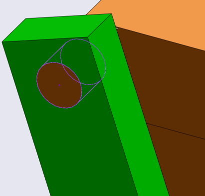
The intention of using these two mates is to replicate a revolute (hinge) joint between the ‘MainBase<1>’ and ‘BeamType2<1>’ parts. So we used a Coincident (Plane-Plane) and a Concentric (Cylinder-Cylinder) mate for this purpose. A Coincident (Plane-Plane) mate contains 1 linear and 2 rotational constraints, and a Concentric (Cylinder-Cylinder) mate contains 2 linear and 2 rotational constraints. So the sum of constraints from these two mates are 7 constraints. But a revolute (hinge) joint should contain 3 linear and 2 rotational constraints. So by introducing these two mates this way, there will be 2 redundant rotational constraints.
Mate configuration 2:
Then, let us find the mates defined between the ‘MateBase<1>’ and
‘BeamType2<1>’ components in the ‘Mate_Config2’ assembly configuration setting.
Mate Type |
Mate Name in the SOLIDWORKS feature tree |
Related Components |
Mate Entity Types |
Snapshot |
|---|---|---|---|---|
Coincident |
Coincident_V_Beam_Back_Left |
MainBase<1> |
Plane |
|
BeamType2<1> |
Point |
|||
Concentric |
Concentric_V_Beam_Back_Left |
MainBase<1> |
Cylinder |
|
BeamType2<1> |
Cylinder |
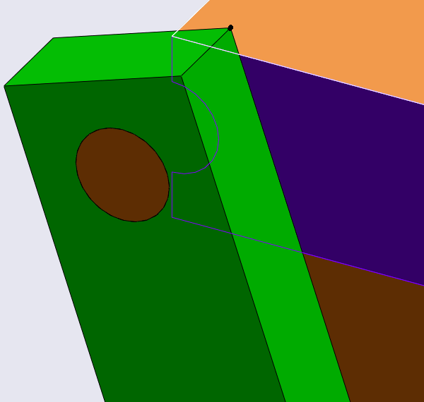
In this ‘Mate_Config2’ configuration, we used a Coincident (Point-Plane) and a Concentric (Cylinder-Cylinder) mate instead. A Coincident (Point-Plane) mate contains only 1 linear constraint. So the sum of constraints from these two mates are 5 (3 linear and 2 rotational). Then the combination of these two mates will work the same as a revolute joint. If you prefer to use the standard mate types of SOLIDWORKS, then you can create revolute joints using a Coincident (Point-Plane) and a Concentric (Cylinder-Cylinder) mate. Or you can use a Coincident (Plane-Plane) and a Concentric (Point-Cylinder) mate instead.
A good feature of SOLIDWORKS, is that SOLIDWORKS can handle some amount of redundant mates if they are well defined, but since we are really interested in the reaction forces of your mechanism, then it is important for us to eliminate the redundancy of mates in the models completely.
In the second configuration, ‘Mate_Config2’, we have applied more similar changes until the model is well-defined without redundant constraints. Basically almost all joints in the model are hinges from a first look and therefore they all need to be reduced to having only five constraints, like explained above. However, it turns out that this is not enough to remove redundancy. What is still missing is that we have closed loops, and making a closed loop with only hinges only works here because all hinges are parallel. In other words, we have a planar mechanism, but if the hinges were not parallel the mechanism would be locked or maybe not even possible to assemble. Some of the “hinges” have here been further reduced so they match what in AnyBody is called a trans-spherical joint (AnyTransSphericalJoint), i.e., a spherical joint which also allows one translation, here along the hinge axis. These joints have only two translational constraints, which implies that they do not carry moments or an axial force.
The selection of these reduced joints, has been made based on the actual joints in the machine, or the assumed actual joints, since this is a constructed case. So the “strong” hinge with good hinge bearings are made as real hinges, while “less strong” joints with clearances and simpler bearings are made as trans-spherical joints.
In the SOLIDWORKS assembly, ‘Mate_Config2’, you can see our choices. We have tried to make it visible by making the “real hinges” with a real cylindrical part fitting a cylindrical hole, whereas the “reduced hinges” have a reduced graphical representation like empty holes or nothing.
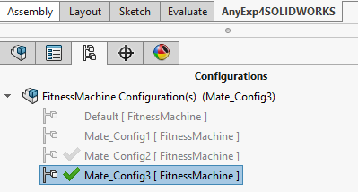
Mate configuration 3:
There is a slightly alternative way to reduce mate redundancy. You can use some
of the mechanical mate types of SOLIDWORKS. Let us change the assembly
configuration to ‘Mate_Config3’ as follows. Here we have entered topologically
the same joint configuration as in ‘Mate_Config2’, but using the mechanical
mates as much as possible. We have named the mates according to the joint type
we want to realize. The trans-spherical joint type does not exist in SOLIDWORKS,
so this has been created with standard mates as in ‘Mate_Config2’.
As you can see in ‘Mate_Config3’, the usage of Hinge mates reduces the total number of mates because a hinge mate requires four mate entities when it is defined with standard mates. The trans-spherical constraint is however realized simply by a Concentric (Point-Cylinder) mate. It will work the same as the AnyTransShericalJoint in AnyBody, but the AnyExp4SOLIDWORKS translator does not realize that it is a joint and will only make a simple object with kinematic constraints as we saw in Lesson 1.
We prefer the solution in ‘Mate_Config3’, since this approach is closer to concepts we normally use with AnyBody, but ‘Mate_Config2’ and ‘Mate_Config3’ are mechanically equivalent.
Translate a SOLIDWORKS Assembly which does not have any Redundant Mates#
Let us translate the assembly under the ‘Mate_Config3’ configuration into an
AnyScript model by using AnyExp4SOLIDWORKS like you did in Lesson 1. You can now
open the model with the newly generated ‘FitnessMachine.main.any’ file, where
you will see the model. Or you can replace the ‘FitnessMachine.any’ file and
all the STl files with the newly created ones, and open your own version of the
main file, ‘My.FitnessMachine.main.any’, where you added the study object and the
rotation driver. Since the mate configurations in Fitnessmachine.any have been
changed, you need to update the inserted driver to the following:
FitnessMachine =
{
  AnyFolder Drivers =
  {
    AnyKinEqSimpleDriver rot_drv =
    {
      AnyKinMeasure& jnt = ..Mates.Hinge_MainCylinder;
      MeasureOrganizer = {0};
      DriverPos = pi/180*{0};
      DriverVel = pi/180*{180};
    };
  };
};
This model will now work, i.e., you can load it, run the ‘Kinematics’ operation in the ‘Study’, and it will do half a revolution of the machine. You can also run the ‘InverseDynamics’ but this will give you the following warning and notice:
WARNING(OBJ.MCH.MUS1): MyFitnessMachine.main.any(27): Study: The muscles in the model are
not loaded due to kinetically over-constrained mechanical system.

NOTICE(OBJ1): MyFitnessMachine.main.any(27): Study.InverseDynamics: No muscles or other
recruited actuators in the model.
The warning is sent because the model contains the same number of independent reaction forces as degrees of freedom. Meaning that these reaction forces carry all directions of the applied load, and if any muscles were added to the model, they would not carry any loads and thus would not be loaded at all. The notice says that the model contains no muscles or other recruited actuators, which entails that we can accept and ignore the warning.
We can now do a simple review of the degrees of freedom of the translated model. Load the model and double-click on ‘Study’ in the model tree to see the object description of the AnyBodyStudy object.
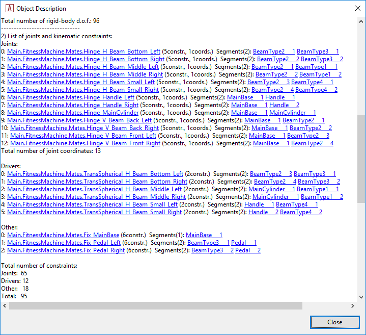
This assembly contains 16 components, i.e., segments. So this assembly has a total of 96 degrees of freedom when disregarding the constraints. It also contains a total of 96 kinematic constraints from the mates and the inserted driver. Since the driver only constrains one degree of freedom, the total number of constraints for the exercise machine is 95, and the one ‘free’ degree of freedom for the machine is driven by the inserted driver.
You can successfully run the ‘Kinematics’ and ‘InverseDynamics’ operations of the AnyBodyStudy object and we are now ready to add the human to the model in the final Lesson 3.