
Lesson 4: Kinematic Measures#
Old tutorial:
This tutorial has not yet been updated to ver. 8 of the AnyBody Modeling System. Some concepts may have changed.
You are not likely to have any sort of idea what a kinematic measure is. Don’t worry - you’re not supposed to know about it. The concept was invented by AnyBody Technology as a way of describing dimensions in a kinematic model that you might want to get information about or control with drivers. A joint angle or a distance between two points are examples of kinematic measures. The position of the center of gravity of the entire model or a subset of its segments are other examples.
If you define a kinematic measure in your model, then you can study its development. But more importantly you can control it. You can add a driver to a kinematic measure, and that way control the movement of the mechanism. Such a driver can be added even when the measure is a less tangible quantity like the collective center of gravity that is not attached to a particular segment.
Joints can be understood as kinematic measures equipped with drivers. For instance, a spherical joint is a distance between two points on two different segments that is driven to be zero. This means that, using kinematic measures, you can define types of joints that are not available as predefined objects in AnyScript.
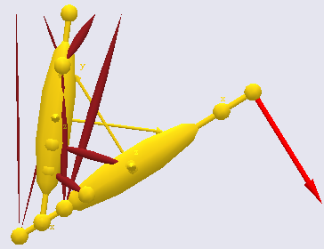
Do you remember the simple arm example of the “Getting Started: AnyScript Programming” tutorial? That was a 2-D model of an arm where we produced the movement by driving the angles of the shoulder and elbow joints directly.
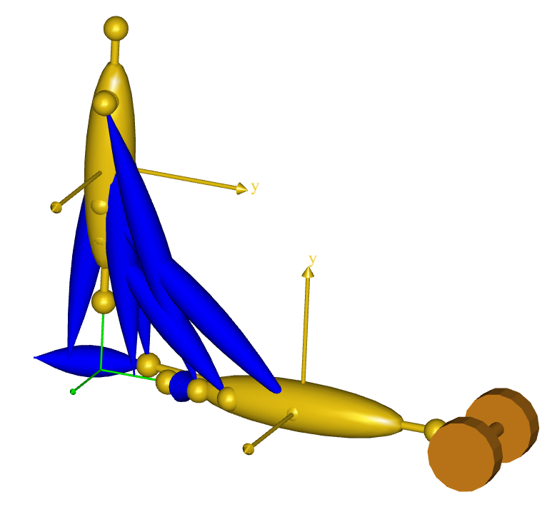
But let us imagine that we wanted the hand to reach out and grab
something at a specific position. It would probably be difficult to
figure out precisely how to drive the two joint angles to put the hand
in the position we wanted it to attain. Instead, we would want to be
able to put the hand (actually the wrist since this simple model has no
hand) directly at the desired position in space and have the elbow and
shoulder joints follow implicitly. This is where the kinematic measures
come into play. Let’s start off with the model just about where we left
in the “Getting Started with AnyScript” tutorial. Please
click here to download the necessary files,
and save it in some working directory on your own hard disk.
Let us try initially to create a kinematic measure that will allow us to track the movement of the wrist. To honor the folder structure of the model we shall create a new folder for the kinematic measure. Let’s place it just below the Jnts folder to reflect the kinship between kinematic measures and joints:
 }; // Jnts folder

 AnyFolder KinematicMeasures = {
    AnyKinLinear WristPos = {

      // These are the nodes that the measure refers to
      AnyFixedRefFrame &Ground = Main.ArmModel.GlobalRef;
      AnyRefNode &UpperArmNode = Main.ArmModel.Segs.ForeArm.HandNode;

      Ref = 0;
    };
  }; // KinematicsMeasures
An AnyKinLinear is a kinematic measure that gauges the spatial vector between two points. The line Ref = 0 means that the coordinates of this linear distance are measured in the coordinate system first of the measure’s end points which in this case happens to be the global reference frame. For other options, please refer to the AnyScript Reference Manual.
So far, we have just added a measure that allows us to track the movement of the hand, but it is still driven by the joint drivers as before. Let’s investigate what we have. Load the model and run a KinematicAnalysis or an InverseDynamicAnalysis, and subsequently open a Chart view.
Expanding the tree though
Main.ArmModelStudy.Output.Model.KinematicMeasures.WristPos will give you
the options shown to the below.
Click Pos, and you will get three graphs tracking the x, y, and z
components of the WristPos kinematic measure.
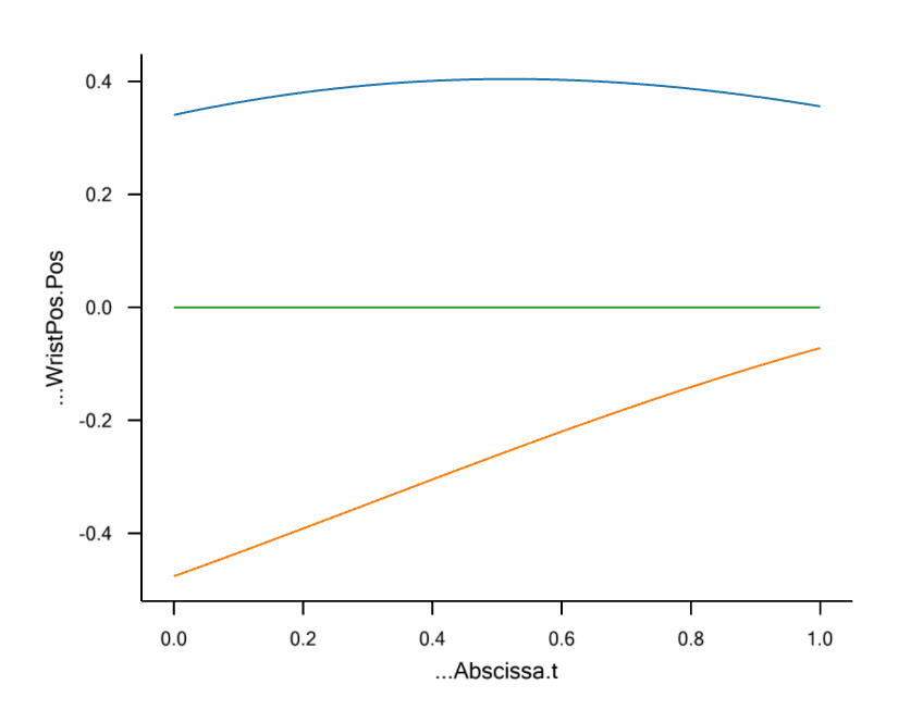
The z component (blue curve) of the measure remains zero throughout the movement because the model is two-dimensional. The top curve (red) is the x component, and the bottom curve (green) is the y component.
Now comes the beauty of kinematic measures: Rather than just observing them, you can actually drive them!
We shall replace the existing drivers on the shoulder and elbow joints by drivers on the x and y components of the WristPos kinematic measure.
We need to remove the existing elbow and shoulder drivers to avoid
kinematic redundancy. You can enclose the drivers in comment characters
/* */, or you can simply erase them, leaving you with an empty
drivers folder:
AnyFolder Drivers = {
}; // Drivers folder
The next step is to fill drivers for the WristPos measure into the Drivers folder. We initially make an empty skeleton. Notice that we are using an AnyKinSimpleDriver here. If you had measured the hand position by a motion tracking technology and wanted to reproduce the movement, you would probably want to use an interpolation driver instead.
AnyFolder Drivers = {
   AnyKinEqSimpleDriver HandMotionXY = {
   };
}; // Drivers folder
We can now fill contents into the HandMotionXY driver that will guide the hand through space:
AnyFolder Drivers = {
  AnyKinEqSimpleDriver HandMotionXY = {
    AnyKinLinear &Jnt = ..KinematicMeasures.WristPos;
    MeasureOrganizer = {0,1};
    DriverPos = {0.4,-0.5};
    DriverVel = {0.2,0.5};
    DriverAcc = {0.0,0.0};
    Reaction.Type = {Off,Off};  // The muscles must do thework
  };
}; // Drivers folder
The first of the red lines above refers to the WristPos kinematic measure. It simply specifies that this is the measure we want to drive. Notice, however that this measure has three components, namely the x, y and z coordinates. But we only want to drive two of them. The MeasureOrganizer handles that problem. It lines up the coordinates of the measure in a row for driving. MeasureOrganizer = {0,1} means that the vectors of driver specifications, such as DriverPos and DriverVel, refer to the x (number 0) and y (number 1) coordinates of the measure.
The values we suggest for DriverPos and DriverVel have been found by inspection of the graphs depicted above showing the development of the measure coordinates when we used the shoulder and elbow drivers. This is good practice because it is so easy to specify wrist positions that the arm cannot reach and thereby provoke a kinematic incompatibility that may be difficult to find in more complex cases.
To conclude, the special feature about kinematic measures is that you
can drive them. In AnyBody, you can drive anything that you can measure,
and this is really a unique facility. If something went wrong for you
along the way, you can download a commented version of the final result
here.
The last lesson in the tutorial on mechanical elements is Lesson 5: Forces.